Antenna Remote Controller
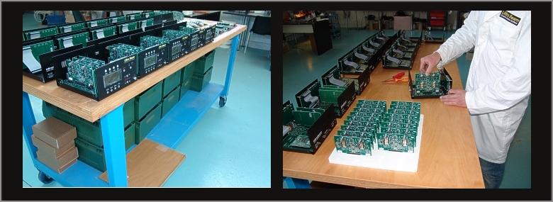
The characteristics of our Antenna Controller are long life and reliability. In the construction of the control unit UltraBeam employs high-quality and rugged material and over-dimensioned components and circuitry. Motor drivers are assembled ad hoc with high performance Transistor Bridges.
We do not choose commercial solution for the electronic board but for guarantee our high standard we design and build by ourselves. A CPU board linearly controls driver Board's parameters such as chopper-current and chopper-frequency and full or half step. The stationing current for each winding is created independently by a constant current generator, which adapts itself to the characteristics of the stepper motor.
The latest Antenna Controller production employs a new LCD display that provides a significant improvement to the contrast ratio and the graphic resolution under any light conditions. The Antenna Controller can be interfaced to most Transceivers through a serial-port and a dedicated cable. It can also remotely controlled through the serial port by means of dedicated software. The serial port offers the possibility to update the Antenna Controller with the latest firmware found here on the “Download” page.
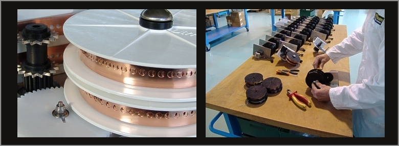
Motor Unit
The mechanics developed by UltraBeam in recent years has reached a very high level of reliability.
All antenna parts are mounted on a single aluminum-plate processed by Computer Numerical Control (CNC), and each single rotating component is mounted on ball bearings.
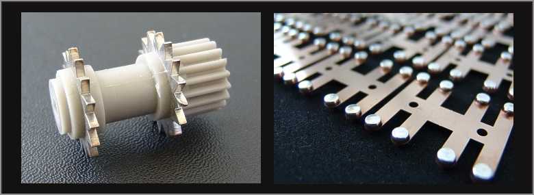
The toothed shaft that moves the copper-beryllium strips is a mono-bloc. To build this important part was necessary to design a special injection mold. During the realization process we take care of the center ax of the two steel sprocket avoiding parallax error resulting into a very reliable and indestructible part.
In 2009 UltraBeam has developed, designed and manufactured the “VRS” system. This brand new system has radically changed the rotation principle of the spools and, consequently, the homing of copper-beryllium strips. The existing Motor Units were less reliable because based, for the retraction of the copper-beryllium, on a spring system.
The VRS ensures the following advantages:
- High mechanical reliability over time
- Less torque required during the rotation of the spools
- Avoid misalignment in case of no-current condition
UltraBeam is proud, with the adoption of “VRS” System, of the best performing and top quality Motor Unit.
Since 2010 the innovative silver sliding contacts ensure excellent mechanical and electrical characteristics.
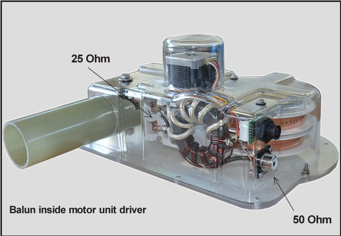
Balun 2:1
All Ultrabeam yagis work with an impedance of approximately 25 Ohms.
For this reason, driven-element motor-units use a 2:1 Balun to transform the 50 Ohm impedance of the feeding-line (coaxial cable) to 25 Ohm to be presented at the feeding-point. For the construction of a very reliable Balun, Ultrabeam hs adopted one of the many projects made by the famous Jerry Sevick (W2FMI) who was and still is, a world-wide reference in the field of transmission-line impedance transformation .The schematic of the Balun requires a special coaxial cable with an impedance of 25 ohm, adequate section and insulation. This is the reason why we do not use commercial coax cable and wrap it by hand in our laboratories.
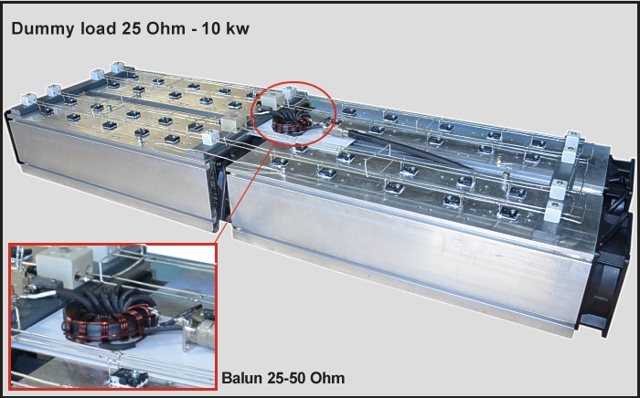
The toroid used is an excellent AMIDON with highly reliable permeability characteristics.
Each hand-made Balun is tested by means of a special UltraBeam produced 25 Ohm dummy load, capable of withstanding a continuous power of 10 kW. Baluns are tested at a much larger power than that reported in our antenna features.
However, since the handling power-capability of antennas is determined by several technical factors, we highly recommend not to exceed the rated power of 3500 Watts PeP.
Final consideration: as the power handling is closely tied to the duration and the mode of transmission, it is almost impossible to determine the real limit power.
Example: a simple "five and nine" can be exchanged without problem with a power of 5 to 6 kW in the SSB or CW modes.
Instead for RTTY transmissions or CONTEST ,is necessary, use one power less than 3500 Watts, this impose a combination of the common sense and good technical knowledge , in relation to high powers in full-time which always distinguish the good radio operator.
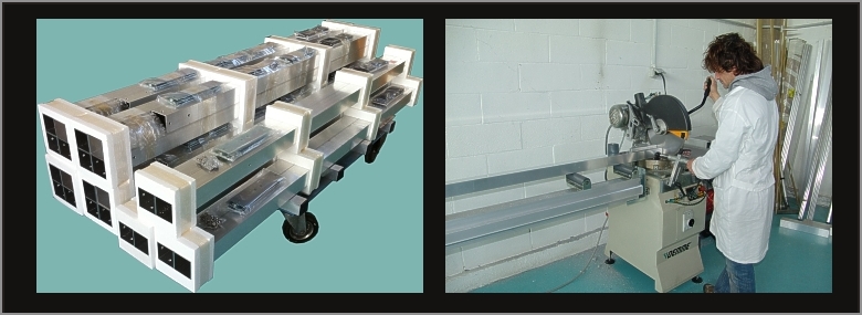
Materials
All hardware, boom, motor support plate, boom-to-mast plate etc. are entirely prepared at our UltraBeam workshops.
The boom uses 6061-T6 aluminum square profiles exclusively produced for UltraBeam.
Square sections and rugged joints make the boom extremely resistant against mechanical and torsional stresses.
All aluminum and stainless-steel antenna parts are Laser-cut and hand-worked with numerically controlled bending machinaries.
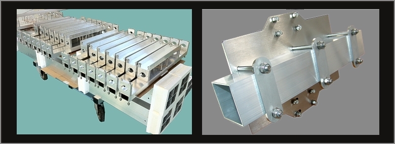
The bracket saddles used in the Motor Unit support plate are CAD-designed and manufactured by special injection-molds.
UltraBeam manufacture is a guarantee of continuous development and quality control of each single component produced.
The whole hardware is exclusively made of AISI 304 stainless-steel.
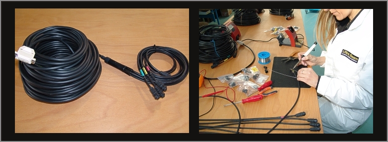
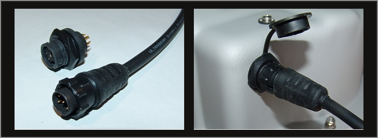
Electrical wiring
Every antenna model includes a wiring harness that connects the Antenna Controller to each Motor Unit.
For an easy and effective connection between the Motor Unit and Antenna, UltraBeam provides a cable fully assembled with multi-polar connectors. This multi polar cable for outdoor use, exclusively produced for UltraBeam by American SwitchCraft Inc, it is provided with waterproof IP68 multi polar gold plated connectors.
Control cables are available in different standard lengths up to 50 meters, but we can also provide on special order any length up to 300 meters.
Once assembled, you can easily and quickly connect the antenna to the Antenna Controller without the risk of any wiring error.